Smart Home Energy Dashboard: Tracking Every Circuit with CT Clamps and MQTT
Installing CT clamp sensors on each circuit breaker and feeding the data into a Home Assistant dashboard via MQTT gives you circuit-level energy visibility for roughly $12-18 per monitored circuit. This is the difference between knowing your house draws 800 watts and knowing the refrigerator compressor is pulling 180 watts for 22 minutes every 90 minutes while the gaming PC idles at 65 watts even when the monitor is off. The hardware is cheap, the wiring is straightforward for anyone comfortable inside an electrical panel, and the software stack — ESPHome or Tasmota on an ESP32, MQTT broker, Home Assistant energy dashboard — runs on hardware you probably already own.
CT Clamp Basics: Split-Core vs Solid-Core
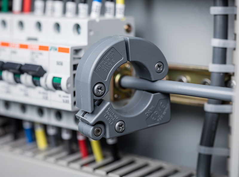
A CT (current transformer) clamp is a passive sensor that clips around a single conductor and measures current via electromagnetic induction — no electrical contact with the wire, no cutting, no stripping. Split-core clamps open on a hinge so you can install them without disconnecting circuits, which makes them the only practical choice for retrofitting an existing panel. Solid-core clamps are slightly more accurate (typically +/-0.5% vs +/-1% for split-core) but require disconnecting and re-terminating the wire through the core, which means shutting down the panel and calling an electrician if you are not licensed to work inside a live breaker box. For a home energy dashboard, a SCT-013-030 split-core clamp (30A, 1V output) costs about $6 each and covers most individual branch circuits; for the main service entrance, step up to a 100A or 200A model (around $12-15).
The critical installation rule: clip the CT around ONE conductor only. A CT clamped around a Romex cable (which contains both hot and neutral in one jacket) measures zero current because the opposing magnetic fields cancel. You must access the individual hot conductor — either at the breaker terminal inside the panel or by separating the conductors in a junction box. This is the mistake that produces hours of debugging in first-time installs, and the fix is always the same: open the panel, find the single hot wire, and reclamp.
ESP32 + CT Clamps: The $25 Multi-Circuit Monitor
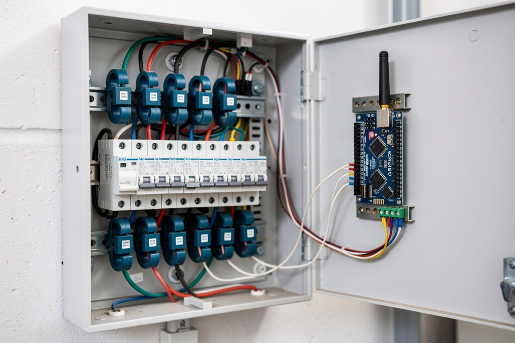
An ESP32 development board costs $5-8 and can read up to 8 CT clamps using its onboard ADC pins, though I recommend a dedicated ADC board like the ADS1115 (16-bit, 4-channel, I2C) for anything beyond 2-3 circuits. The ESP32’s built-in ADC is 12-bit with significant noise below 100mV — fine for rough whole-house monitoring but not accurate enough for individual 15A lighting circuits that draw under 50 watts most of the time. Here is the component stack that covers 8 circuits for under $80 total:
| Component | Purpose | Approximate Cost | Per-Circuit Cost (8 circuits) |
|---|---|---|---|
| ESP32 Dev Board (Wemos D1 Mini ESP32) | Microcontroller + Wi-Fi | $6 | $0.75 |
| 2× ADS1115 ADC Module | 16-bit analog-to-digital (8 channels) | $14 | $1.75 |
| 8× SCT-013-030 Split-Core CT | 30A current sensors | $48 | $6.00 |
| 1× SCT-013-000 (100A) | Main service entrance monitoring | $12 | N/A |
| Breadboard + jumper wires + 3.3V regulator | Prototyping and power | $5 | $0.63 |
| 3D-printed enclosure | Mounting and isolation | $2 (filament) | $0.25 |
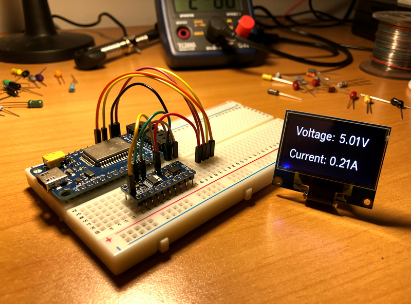
The ESP32 runs ESPHome, which handles the ADC sampling, calibration, and MQTT publishing in roughly 50 lines of YAML. ESPHome’s CT clamp sensor component includes a built-in sampling window and RMS calculation, so you do not need to write signal-processing code — just wire the CT output through a burden resistor and voltage divider to the ADC input, calibrate against a known load (a 100W incandescent bulb is the simplest calibration source), and the data appears in Home Assistant as a sensor entity named sensor.circuit_1_power with watts, amps, and accumulated kilowatt-hours.
MQTT Topics and Dashboard Design
Each circuit publishes to a structured MQTT topic hierarchy that Home Assistant auto-discovers via the MQTT integration. A typical topic pattern looks like:
home/energy/circuit_1/watts → 182.4
home/energy/circuit_2/watts → 45.1
home/energy/main/watts → 1247.8
home/energy/main/kwh_total → 38472.3
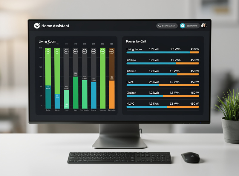
The Home Assistant energy dashboard pulls these entities into a circuit-by-circuit breakdown that answers the questions a whole-home monitor cannot: why is the baseline draw 400 watts at 3 AM, which circuit has the vampire load that costs $8/month, and whether the EV charger and dryer running simultaneously trips the main breaker or just approaches it. The dashboard card I use displays six circuits as bar charts with 24-hour totals, color-coded by whether each circuit is above or below its own 7-day average — a single glance tells me if something anomalous is running.
For the full picture of what happens downstream of the panel — how inverters handle monitored loads, how battery storage integrates with circuit-level data, and what MQTT topics a hybrid inverter exposes natively — the smart inverter MQTT monitoring guide on BatteryStorageHQ covers the energy-storage side of this equation, which is the natural next step once you can see what every circuit draws.
As an Amazon Associate I earn from qualifying purchases.
My Real-World Experience With This Setup
The gap between spec-sheet energy monitoring and what actually changes your behavior is the dashboard. I ran CT-clamp monitoring on my panel for three months before I looked at the data more than once a week. What changed was adding a Home Assistant dashboard card on the kitchen tablet showing live whole-home draw — seeing the 400-watt spike when the electric water heater kicked in made me shift it to a timer window. The monitoring did not save energy by itself; the visibility did.
The single most useful data point from months of monitoring was identifying the standby load: the devices that draw power 24/7 even when “off.” My TV, AV receiver, cable box, and network gear together pulled 45 watts continuously — about $50 a year for nothing. A single smart strip with a master/slave cut dropped that to 3 watts. That $25 strip paid for itself in six months, and the monitoring is what found it.
The MQTT pipeline is what turns CT-clamp data from a passive display into an automation input. Each circuit in my setup reports to Home Assistant via MQTT every 5 seconds, and HA triggers automations based on thresholds — the dryer circuit dropping below 5 watts fires the laundry-done notification, and the garage opener spiking above 300 watts for more than 30 seconds activates the door-open check. That circuit-level granularity is what CT clamps give you over a whole-home monitor: you know exactly which circuit is doing what, not just the aggregate draw. The ESP32 and ADS1115 combination costs about $40 in parts and an afternoon of soldering — the cheapest path to circuit-level energy visibility I have found, and the MQTT integration into Home Assistant means the data flows into the same rule engine that runs the rest of the house.
Frequently Asked Questions
What is a CT clamp and how does it work?
A CT (current transformer) clamp is a passive sensor that clips around a single electrical conductor and measures AC current via electromagnetic induction. It requires no electrical contact with the wire and outputs a small voltage proportional to the current flowing through the conductor. Split-core clamps open on a hinge for tool-free installation on existing circuits.
Can I install CT clamps without an electrician?
Split-core CT clamps can be installed without disconnecting circuits, but you must work inside the electrical panel where exposed bus bars carry lethal current. If you are not comfortable around live panels, hire an electrician. The sensor itself requires no cutting or stripping — it simply clips around an individual hot conductor at the breaker terminal.
How many CT clamps does an ESP32 support?
An ESP32 with two ADS1115 16-bit ADC modules supports up to 8 CT clamps with per-circuit accuracy. Without external ADCs, the ESP32’s built-in analog pins can handle 3-4 circuits but with reduced accuracy below 100 watts. Add one more CT clamp for the main service entrance to compare total draw against the sum of individual circuits.
How accurate are home CT clamp energy monitors?
Split-core CT clamps with a 16-bit ADC achieve approximately +/-1-2% accuracy for loads above 100 watts and +/-5% for loads under 50 watts. This is sufficient for circuit-level monitoring where you want to identify which circuit is drawing anomalous power, not bill customers with utility-grade precision. Calibrate each clamp against a known resistive load for best results.
What software do I need to run a CT clamp energy dashboard?
ESPHome or Tasmota on the ESP32 microcontroller reads the CT clamps and publishes to MQTT. Home Assistant receives the MQTT data and displays it in the built-in energy dashboard. The entire software stack is free and open-source, runs on a Raspberry Pi or always-on PC, and requires no cloud subscription.
Why does my CT clamp read zero when clamped around a cable?
A CT clamp must be clipped around a single hot conductor only. Clamping around an entire Romex cable (which contains both hot and neutral) measures zero current because the opposing magnetic fields from the two conductors cancel each other out. Access the individual hot wire at the breaker terminal inside the panel for accurate measurement.
Related Articles
- Whole-Home Energy Monitor vs Smart Plugs: Which Should You Choose?
- Complete Smart Home Energy Audit Guide
- Best Smart Home Energy Management Systems 2026
- How to Reduce Your Electric Bill with Smart Home Devices
- Smart Home Energy Monitoring for Renters